---
title: "14.1 General"
chapter: "14 Mapping BPMN Models to WS-BPEL"
source: "OMG BPMN 2.0.2 — formal/2013-12-09"
pages: "445-446"
---
> 14 Mapping BPMN Models to WS-BPEL · páginas 445-446 · [índice](../README.md)
## 14.1 General
**NOTE:** The contents of this clause is REQUIRED for BPMN BPEL Process Execution Conformance or for BPMN Complete Conformance. However, this clause is NOT REQUIRED for BPMN Process Modeling Conformance, BPMN Process Choreography Conformance, or BPMN Process Execution Conformance. For more information about BPMN conformance types, see page 1. This clause covers a mapping of a **BPMN** model to WS-BPEL that is derived by analyzing the **BPMN** objects and the relationships between these objects. A **Business Process Diagram** can be made up of a set of (semi-) independent components, which are shown as separate **Pools**, each of which represents an orchestration **Process**. There is not a specific mapping of the diagram itself, but rather, each of these *orchestration* **Processes** maps to an individual WS-BPEL *process*. Not all **BPMN** *orchestration* **Processes** can be mapped to WS-BPEL in a straight-forward way. That is because **BPMN** allows the modeler to draw almost arbitrary graphs to model control flow, whereas in WS-BPEL, there are certain restrictions such as control-flow being either block-structured or not containing cycles. For example, an unstructured *loop* cannot directly be represented in WS-BPEL. To map a **BPMN** orchestration **Process** to WS-BPEL it MUST be *sound*, that is it MUST contain neither a *deadlock* nor a *lack of synchronization*. A deadlock is a reachable state of the **Process** that contains a *token* on some **Sequence Flow** that cannot be removed in any possible future. A lack of synchronization is a reachable state of the **Process** where there is more than one *token* on some **Sequence Flow**. For further explanation of these terms, we refer to the literature. To define the structure of **BPMN Processes**, we introduce the following concepts and terminology. The **Gateways** and the **Sequence Flows** of the **BPMN** orchestration **Process** form a directed graph. A *block* of the diagram is a connected sub-graph that is connected to the rest of the graph only through exactly two **Sequence Flows**: exactly one **Sequence Flow** entering the block and exactly one **Sequence Flow** leaving the block. A *block hierarchy* for a **Process** model is a set of blocks of the **Process** model in which each pair of blocks is either nested or disjoint and which contains the maximal block (i.e., the whole **Process** model) A block that is nested in another block B is also called a *subblock* of *B* (cf. Figure 14.1). Each block of the block hierarchy of a given **BPMN** orchestration **Process** has a certain structure (or pattern) that provides the basis for defining the BPEL mapping.
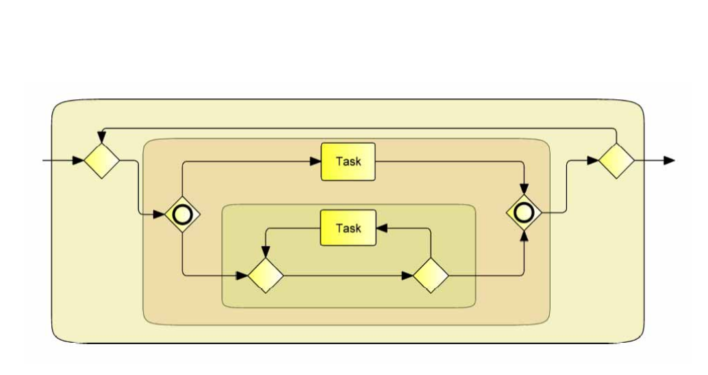
*Figure 14.1 – A BPMN orchestration process and its block hierarchy* (p. 446)
The following sub clauses define a syntactical BPEL mapping prescribing the resulting BPEL model at the syntactical level, and a semantic BPEL mapping prescribing the resulting BPEL model in terms of its observable behavior. The syntactical BPEL mapping is defined for a subset of **BPMN** models based on certain patterns of **BPMN** blocks, whereas the semantical BPEL mapping (which extends the syntactical mapping) does not enforce block patterns, allowing for the mapping of a larger class of **BPMN** models without prescribing the exact syntactical representation in BPEL.